Concepts and Background
This section briefly introduces key concepts and motivations underpinning DALiuGE.
Dataflow
A traditional dataflow computation model does not explicitly place any control or
constraints on the order or timing of operations beyond what is inherent in the
data dependencies among compute tasks. The removal of explicit scheduling of
compute task in the dataflow model has opened up new (e.g. parallelism)
opportunities that are previously masked by “artificial” control flow imposed by
applications or programmers. A similar example is the make tool, where the
programmer focuses on defining each target and its dependencies. The burden of
exploring parallelism to efficiently execute many individual compiling tasks in
a correct order lies within the responsibility of the make utility.
Graph
Following the dataflow model, a computer program can be described by a Directed Graph where the nodes denote compute task, and the edges denote data dependencies between operations. In principle, a dataflow graph consists of edges, nodes (or actors), and tokens. Tokens represent data items and travel across directed edges to be transformed at nodes into other data items (similar to functions). While in theory the dataflow model provides a powerful yet simple formalism to describe parallel computation, early efforts in developing dataflow architecture had to introduce control flow operators (e.g. switch and merge) and data storage mechanism in order to put dataflow models into practice.
Data-driven
In developing the DALiuGE prototype, we have extended the “traditional” dataflow model by integrating data lifecycle management, graph execution engine, and cost-optimal resource allocation into a coherent data-driven framework. Concretely, we have made the following changes to the existing dataflow model:
- Unlike traditional dataflow models that characterise data as “tokens” moving across directed edges between nodes, we instead model data as the node, elevating them as actors who have autonomy to manage their own lifecycles and trigger appropriate “consumer” applications based on their own internal (persistent) states. In our graph model, both application (task) and data nodes are termed as DROPs. What are really moving on the edge are Drop Events.
- While nodes/actors in the traditional dataflow are stateless functions, we express both computation and data nodes as stateful DROPs. Statefulness not only allows us to manage DROPs through persistent checkpointing, versioning and recovery after restart, etc., but also enables data sharing amongst multiple processing pipelines in situations like re-processing or commensal observations. All the state information is kept in the Drop wrapper, while the payload of the Drops, i.e. pipeline component algorithms and data, are stateless.
- We introduced a small number of control flow graph nodes at the logical level such as Scatter, Gather, GroupBy, Loop, etc. These additional control nodes allow pipeline developers to systematically express complex data partitioning and event flow patterns based on various requirements and science processing goals. More importantly, we transform these control nodes into ordinary DROPs at the physical level. Thus they are nearly transparent to the underlying graph/dataflow execution engine, which focuses solely on exploring parallelisms orthogonal to these control nodes placed by applications. In this way, the Data-Driven framework enjoys the best from both worlds - expressivity at the application level and flexibility at the dataflow system level.
- Finally, we differentiate between two kinds of dataflow graphs - Logical Graph and Physical Graph. While the former provides a higher level of computation abstraction in a resource-independent manner, the latter represents the actual execution plan consisting of inter-connected DROPs mapped onto a given set of hardware resources in order to meet performance requirements at minimum cost (e.g. power consumption).
DALiuGE Functions
The DALiuGE prototype provides eight Graph-based functions as shown in Fig. 1.
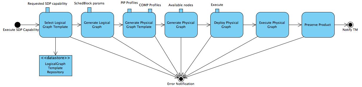
Fig. 1 Graph-based Functions of the DALiuGE Prototype
The Graphs section will go through implementation details for each function. Here we briefly discuss how they work together in our data-driven framework.
- First of all, the Logical Graph Template (topleft in Fig. 1) represents high-level data processing capabilities. In the case of SDP, they could be, for example, “Process Visibility Data” or “Stage Data Products”.
- All logical graph templates are managed by the LogicalGraph Template Repository (bottomleft in Fig. 1). The logical graph template is first selected from this repository for a specific pipeline and is then filled with scheduling block parameters. This generates a Logical Graph, expressing a pipeline with resource-oblivious dataflow constructs.
- Using profiling information of pipeline components and COMP hardware resources, the DALiuGE prototype then “translates” a Logical Graph into a Physical Graph Template, which prescribes a manifest of ALL DROPs without specifying their physical locations.
- Once the information on resource availability (e.g. compute node, storage, etc.) is presented, DALiuGE associates each DROP in the physical graph template with an available resource unit in order to meet pre-defined requirements such as performance, cost, etc. Doing so essentially transforms the physical graph template into a Physical Graph, consisting of inter-connected DROPs mapped onto a given set of resources.
- Before an observation starts, DALiuGE deploys all the DROPs onto these resources as per the location information stated in the physical graph. The deployment process is facilitated through DROP Managers, which are daemon processes managing deployed DROPs on designated resources.
- Once an observation starts, the graph Execution cascades down the graph edges through either data DROPs that triggers its next consumers or application DROPs that produces its next outputs. When all DROPs are in the COMPLETED state, some data DROPs are persistently preserved as Science Products by using an explicit persist consumer, which very likely will be specifically dedicated to a certain science data product.